Clappers#
This chapter covers:
- Background: The various types of clappers, how they are made and suspended within the bell
- Routine Checking: The ways in which clappers can be checked, both as part of a routine maintenance schedule and to investigate any problems
- Maintenance: The options for dealing with problems and the level of experience needed to carry them out
- Final sections cover: Other Information relevant to clappers and Further Reading
Background#
A clapper assembly comprises four main components:
- The crown staple, from which the clapper is suspended
- The clapper ball, which strikes the bell
- The shaft, connecting the ball to the crown staple, via the top end of the clapper
- The flight, which adds mass below the ball to improve the dynamic behaviour of the clapper
Types of clappers#
There are three main types:
- Traditionally, clappers were made from wrought iron. This has a low carbon content with slag inclusions which form a fibrous structure as the material is forged (or ‘wrought’) into a finished product. This material is tough, malleable, ductile, corrosion resistant and easily forge welded. It is an ideal material for producing a clapper. Unfortunately, it is now difficult to source.
- Faced with the difficulty of obtaining wrought iron, ductile iron, also known as spheroidal graphitic (or ‘SG’) cast iron, became the material of use for clappers. This is iron containing a high level of carbon (around 3%). Unlike the more familiar form of cast iron, where the carbon forms inclusions in the shape of flakes, ductile iron includes alloying elements which result in the carbon forming nodular inclusions, giving a tougher material. Being cast, rather than forged, the shape of the casting pattern is important. Some early SG clappers had oversized shafts, balls and flights which could lead to handling and striking problems, as well as possible damage to the bell. It is possible to machine such clappers to a better profile but this must be done by a specialist. Steel clappers have been made but are not widely used.
- Since 2005, an increasing number of bells are fitted with wooden shafted clappers. If well designed, these may improve the handling of ‘awkward’ bells and make it easier to raise large bells ‘right’ – see Wooden Shafted Clappers. ‘Composite clappers’ are also available: these use a man-made material for the shaft.
Clapper suspension – historical#
This section describes historical clapper designs to allow a Steeple Keeper to recognise them. The maintenance and repair of such clappers is a specialist task and advice should be sought from a bell hanger.
Up until the mid-19th century, clappers were suspended from a U-shaped wrought iron staple, cast into the crown of a bell during its manufacture. Iron corrodes with time and the corroded staple expands in the crown of the bell, generating stresses which will ultimately lead to cracking of the bell. For this reason, cast-in crown staples must be removed if the bell is to be retained for ringing – see Removal of a cast-in crown staple.
The clapper was usually suspended from a cast-in crown staple using a baldric (or ‘baldrick’). In the nineteenth century, in the absence (or after the removal) of a cast-in crown staple, a separate ‘centre bolt’ would be passed up through the crown of the bell and headstock. The traditional suspension would be made from a stirrup at the bottom of this bolt, with a baldrick or using a wooden block arrangement – for example, the ‘Rudhall wooden top’ shown in Figure 1.
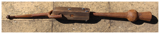
Figure 1: Wrought iron clapper with Rudhall wooden top
Modern independent clapper assemblies#
In modern installations, the clapper is suspended from an independent crown staple, with a centre bolt passing up through the crown of the bell and the headstock. The component parts, shown in Figure 2, are:
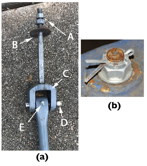
Figure 2: Parts of an independent crown staple
- A fixing nut at the top of the headstock. There are several
possibilities for this:
- The most common is a castellated nut held in place with a split pin, shown in Figure 2(b). Stainless steel split pins are preferred to avoid corrosion and they may need to be replaced after removal.
- A plain nut with a split pin above – the nut may work loose but should not come off completely.
- A nut plus a locknut, shown at (A) on Figure 2(a).
- A nut with a sacrificial plastic insert – this type must be replaced every time the nut is removed.
- Proprietary locking nuts with a metallic spring section that clamps to the thread.
- A steel washer between the nut and the top of the headstock (not included on Figure 2(a) but visible on Figure 2(b)).
- The part of the centre bolt within the headstock is often of square section.
- Under the crown of the bell is the crown staple washer, made of leather or fibre, (B) on Figure 2(a). When the centre bolt nut is tightened, this helps to lock the crown staple in position within the bell. This is particularly important where the inside of the crown of the bell is rough – for example where the bell has been quarter turned.
- At the bottom of the crown staple is usually a clevis fitting, (C) on Figure 2(a), comprising a U-shaped yoke with a pivot pin supporting the clapper – described in the following section.
Pivot pin and clapper bushes#
Some designs of wooden shafted clappers have a ball bearing suspension. This is outside the scope of this document.
The U-shaped clevis has two holes to accommodate a pivot pin. Usually, one hole and one end of the pin are threaded. After insertion, the threaded end of the pin protrudes through the clevis and is secured by a locknut – shown at (D) on Figure 2(a). The other end of the pin has a bolt head or machined flats to allow a spanner to hold the pin while the locknut is tightened. If a bolt head is present, care must be taken not to overtighten as this could crack a cast staple or bend a steel one.
The top end of the clapper has a hole through which the pivot pin passes, fitted with a replaceable bush. Various types of bushes may be encountered:
Traditionally, clapper bushes were made of lignum vitae. This is a dense wood (it sinks in water) containing oils which provide some natural lubrication. It is ideal as a bearing material and has been used for bearings in hydro-electric plants and nuclear submarines. Unfortunately, the source trees are now regarded as ‘Near Threatened’ making further use of this material unsustainable. If worn lignum vitae bushes are encountered, they must be replaced – this is outside the scope of this document.
Clapper bushes made from lignum vitae require additional lubrication, either by a screw cap lubricator of the ‘Stauffer’ type or a grease nipple. Although more modern types of metal or plastic bushes may require no lubrication some bell hangers still provide grease nipples or similar, as shown at (E) on Figure 2(a). On balance, a method of lubrication is preferred although the benefit of retrospective fitting may be small.
Modern types of clapper bush are made of:
- Oil impregnated sintered phosphor bronze.
- Nylon. Experience with a problem of swelling when damp or at elevated temperature means such bushes are now rarely fitted. Existing nylon bushes need not be replaced if performing satisfactorily. If necessary, the swelling problem can be rectified by careful reaming.
- TUFNOL. This is a proprietary laminated material impregnated with phenolic resin.
Bushes may be backed by a layer of rubber.
Clapper centring pins#
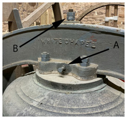
Figure 3: Twiddle pin (A), and double crown staple locknut (B)
While not strictly part of the clapper, it is appropriate to mention these here.
Most modern rings of bells with cast iron or fabricated steel headstocks have clapper centring pins fitted – usually known as ‘Twiddle Pins’. There is clearance where the crown staple passes through the bottom of the headstock and the crown of the bell: twiddle pins allow the crown staple to be positioned in the centre of the bell. There is a twiddle pin on either side of the headstock, one of which can be seen at (A) on Figure 3. Each pin comprises a machine screw which locates against the generally square section of the centre bolt. The crown staple can be positioned by slackening one pin and tightening the other. Locknuts on each pin allow the pins to be locked in place when the process is complete. (Figure 3 also shows (B) another example of double locknuts on the crown staple.)
The use of twiddle pins to correct an odd-struck bell is described in Odd-Struck Bells.
Checking Clappers#
This Section deals with initial and regular checks of clappers. Routine checks and maintenance should be carried out in accordance with a schedule - see Maintenance Schedule - and results of all checks, including issues raised and how they were resolved, should be recorded.
For both practical and safety reasons, the checking and any subsequent maintenance must be carried out by at least two people, taking account of Health & Safety Requirements. The checks described here can be carried out by a Typical Steeple Keeper and helpers on the more modern independent crown staple designs; checks on the older types of clapper suspension may require assistance from more experienced personnel.
The procedure for checking is as follows:
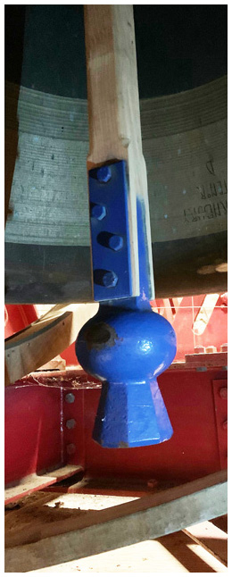
Figure 4: Wooden shafted clapper - note bolts securing ball to shaft
Procedure for checking a clapper
Standing in the pit, swing the clapper to check for squealing or grinding noises. It should swing smoothly and noiselessly, for more than five swings. (Take care to avoid getting hit by the swinging clapper!) If not, this could indicate problems with the clapper bush. If the clapper has provision for lubrication this should be used.
Check the clapper is swinging ’true’ – that is, the axes of rotation of the bell and the clapper are parallel. This can be checked by loosely holding the clapper vertical while a helper swings the bell through a small angle. If the clapper is not true it will move slightly sideways as the bell swings. Correction of this problem is described in Clapper not swinging true.
If this is a first check, assess the extent of the clapper impact area on the inside of the bell. If elongated this indicates wear of the clapper bush.
If the bell has a wooden clapper, this is a good time to check the tightness of the bolts securing the shaft to the clapper ball (see Figure 4) and the top fitting. For all clapper types, also check the locknut on the pivot pin. These fittings are subject to vibration, especially if the bush is worn, and it is not unknown for the pivot pin to work its way out and lead to ejection of the clapper. The consequences of this are similar to those of a broken clapper.
Check the movement of the clapper by attempting to lift the clapper vertically while a helper holds the crown staple nut lightly (if twiddle pins are present, slacken one of them first). On a well-maintained bell, there should be no vertical movement of the crown staple nut. When finished, remember to re-tighten the twiddle pin.
There are two main reasons why movement might occur:
The nut may have worked loose. This is unlikely with a castellated nut and split pin or a proprietary type of locknut but might occur with other types of nuts. The corrective action is described in Correcting loose crown staple nut.
The crown staple washer may be damaged or have become compressed.
With the crown staple tight on the crown of the bell, there may still be some small vertical movement arising from play in the clapper bush. This can be investigated further by the sideways movement of the clapper – sometimes termed “clapper roll”. This is a sensitive measurement as a small movement in the bush is magnified by the length of the clapper. Clapper roll is measured most easily by standing in front of the bell with the clapper pulled to touch the rim. The total extent (left to right) of sideways movement can then be measured. The amount of roll should be checked and recorded on each occasion to provide a history of bush wear and to give warning of the need for re-bushing. As a guide, clapper roll over 20mm is warning of a need to plan for re-bushing and over 50mm requires immediate attention. A sudden large increase in clapper roll may indicate breakage of the pivot pin.
If the bells have not been inspected for a long time, wear of the bush will also be revealed by an elongated impact area on the bell.
It will be necessary to remove the clapper to investigate (a) noise from the swinging clapper, (b) excessive clapper roll, or (c) possible damage to the crown staple washer or pivot pin – clapper removal is described in Removal and replacement of a clapper.
Maintenance#
Removal of a cast-in crown staple#
Removal of a cast-in crown staple must be carried out by a professional Bell Hanger, commonly within their workshop. Note that, within the jurisdiction of the Church of England, this work will require a faculty.
Clapper not swinging true#
When working under small bells it may be necessary to remove the slider (if present) to provide better access. You MUST check it has been replaced correctly when the work is complete.
Correction of a clapper which is not swinging true is within the capability of a Typical Steeple Keeper.
Procedure for correcting a clapper not swinging true
- Slacken off one twiddle pin if present.
- Helper just slackens the crown staple nut.
- Steeple Keeper loosely holds the clapper vertical and checks for sideways movement as the helper swings the bell through a small angle.
- The Steeple Keeper twists the clapper to correct the swing and repeats step 3 until satisfied that the clapper is swinging true.
- Steeple Keeper holds the clapper in the correct position against the edge of the bell while the helper tightens the crown staple nut and, if fitted, the twiddle pin.
- Repeat step 3 to check that the clapper is still swinging true – over-enthusiastic re-tightening of the crown staple nut may rotate the crown staple.
Record a note to repeat the check at the next maintenance session. The clapper will need removal for further investigation if the problem recurs.
Correcting loose crown staple nut#
As in replacement of the clapper described below.
Removal and replacement of a clapper#
Using local effort to remove and replace a clapper is valuable, since it saves a bell hanger the time and expense of travel to do this small part of the work.
Removal and replacement of a clapper is within the capability of a Typical Steeple Keeper, even if rectification of any problems requires specialist services.
Procedure for removal of a clapper
- Remove the split pin if present. Slightly loosen the crown staple nut, ideally using the correct size spanner, although a large adjustable spanner is a possible alternative. This may require some effort.
- If twiddle pins are present, slacken one. Alternatively, slacken both by the same number of turns.
- Using tape or a marker pen, mark the ground pulley side of the clapper and the crown staple. This is to ensure that the clapper is replaced in the original orientation.
- A helper stands in the pit ready to support the clapper while the Steeple Keeper removes the crown staple nut. The Steeple Keeper must warn the helper just before the nut comes off the thread. The nut and washer are replaced for safe keeping on the crown staple after removal.
With the assembly removed, any problems with a worn bush, failure of a pivot pin or a damaged crown staple washer will usually be obvious. Any problems can be rectified either by a local engineering specialist or a Bell Hanger. If this involves disassembly of the clapper, the contractor must be required to replace it in the original orientation, using the marks made on the clapper and crown staple in item 3 above.
Note that the traditional leather or fibre washers may compress gradually and be more easily damaged by movement. Harder materials are available and advice on this should be sought from a Bell Hanger.
Replacement of the clapper follows the reverse procedure, ensuring that:
- The clapper is replaced in the original orientation and is swinging true – see Clapper not swinging true.
- The twiddle pin or pins, if present, is/are tightened. This is done with the crown staple nut just tight (“nipped up” seems to be the technical term).
- The crown staple nut is tightened. A rule of thumb is to use reasonable force applied to a 10 inch (25cm) spanner.
- A final check is carried out to ensure the clapper is swinging true.
The precautions described above to replace the clapper in the same orientation should ensure that the clapper will not become odd-struck (assuming it was not originally odd-struck). If the clapper has not been marked or reassembled incorrectly it will be necessary to check the odd-struckness and correct as necessary – see Odd-Struck Bells.
Finally, details of the work carried out are recorded for future reference.
If you are working on a bell where the clapper has not been removed for some time, you may find that the crown staple nut and twiddle pins (if present) have become seized. The first step is to treat them with a penetrating oil, preferably overnight, and then attempt to use a large spanner or wrench. If this is not effective, some form of impact driver may be more successful. Trying to hammer the spanner or wrench is not preferred, as it may lead to damage, both to the installation and to yourself. If all else fails, don’t be afraid to call on outside help. To avoid this in the future, coat the threads with an anti-seize copper grease before replacing.
Other Information#
Odd-struck bells#
Ideally, the time it takes for a bell to strike after being pulled off at handstroke should be equal to the time at backstroke. Many ringers will have visited towers where they are warned that a certain bell is “a bit slow at handstroke” or something similar. But this should not be the case for a modern bell with the clapper hanging in the centre of the bell at rest.
We are assuming here that all the checks and maintenance described above have been carried out. This should have eliminated problems caused by clappers not running freely, worn bushes, loose crown staples and so on. All of these could result in unpredictable odd-struckness. But, as a responsible Steeple Keeper, you will have already ruled out all of these.
A bell that is noticeably odd-struck and has twiddle pins can be corrected as follows:
Procedure for correcting odd-struckness
- With the bell down, pull up the rope and secure it to take the weight of the rope off the wheel. The bell should now be at bottom dead centre of its rotation. If possible, check this with a straight edge and a spirit level across the mouth of the bell. (A bell on plain bearings may need nudging for it to settle at bottom dead centre.)
- Slightly loosen the crown staple nut.
- Standing facing the bell, touch the end of a tape measure against the striking surface on the clapper ball (taking care not to move the clapper) and read the measurement to the lip of the bell.
- Repeat this on the opposite side (it helps to have one person on each side).
- If the readings are different, slacken one twiddle pin and tighten the other.
- Repeat steps 3 to 5 until the two measurements are equal, ideally to within 1mm.
- Re-tighten the crown staple nut and twiddle pins, and re-instate the bell rope.
If twiddle pins are not present, the recommendation is to place a tapered washer (or a half-washer) under the crown of the bell. Advice on this should be sought from a specialist.
Electronic devices are available for measuring odd-struckness – as described in Odd-struckness and swing periods. It may be possible to find someone able to offer this as a service – perhaps in your local Guild or Association. Such a device can also offer useful data on the swing periods of bells and the comparison between all bells in the ring – see also in Odd-struckness and swing periods. While outside the scope of this document, this may be worth investigating as a way of dealing with problems in striking for some rings of bells.
Clapper breakage#
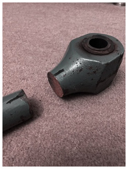
Figure 5: SG cast iron clapper broken at the top end
The consequences of a broken clapper (Figure 5) can be serious, with the flying clapper causing expensive damage - maybe even breaking another bell.
In the event of breakage, the steeple keeper must check all parts of the installation for any consequential damage.
Failures such as that shown in Figure 5 usually occur in SG clappers and result from a fatigue crack initiated from a pre-existing defect, leading to failure when the crack reaches a critical size. This type of crack is almost impossible to detect before failure without the use of specialised equipment and certainly not with the clapper in place within the bell.
Broken clappers, either SG or wrought iron, cannot be repaired by electric welding. For an SG clapper, the answer is a new clapper. Wrought iron clappers can be repaired by forge welding – in fact, many wrought iron clappers are made in two parts which are then forge welded to the correct length. But this work must be carried out by a specialist.
Another possible cause of clapper failure is the pivot pin working loose and eventually falling out. This is something which should be detectable at an early stage and rectified during regular checks.
In summary, any repairs or replacements for clappers must be carried out by a Bell Hanger. A Typical Steeple Keeper can play a part by removing the remains of the clapper and by installing the new or repaired one.
Worn clapper ball#
Wear on the striking face of the clapper ball should be checked during routine maintenance. If a substantial flat surface has developed this is a job for a Bell Hanger, although the Steeple Keeper can assist by removing and replacing the clapper. The Bell Hanger may be able to twist and re-forge the shaft of a wrought iron clapper to present a new striking face.
Bell going up wrong#
Some bells, particularly those over 20 to 25 cwt, are prone to going up ‘wrong’. That is, the clapper is on the higher (wrong) side of the bell when it is set at handstroke after raising. For some bells, it may be difficult to set the bell when this occurs. This depends on the design of bell and clapper – more specifically, on (a) the distance between the two axes of rotation of bell and clapper, and (b) the low amplitude swing periods of the bell and clapper. As a rough guide, the low amplitude swing period of the clapper should be at least 90% that of the bell.
Rectification is a job for specialists. Replacement with a wooden shafted clapper may help.
Further Reading#
Wooden shafted clappers#
Bernard Taylor provides a history of the development of wooden shafted clappers in: “Wheeler’s Wooden Wallopers”. The Ringing World 2020 (5721): 1258-1261. Several other suppliers now provide their own designs.
Odd-struckness and swing periods#
David Bagley describes a meter for measuring odd-struckness in “Oddstruckness – What it is and how to measure it”, The Ringing World 2019 (5653): 840-841.
Bernard Taylor describes work on swing periods and the matching of bells within a ring in “Creating a well-balanced ring at Worcester”, The Ringing World 2019 (5686): 388-391, (5694): 582-585 and (5679): 652-653.
Image Credits#
| Figure | Details |
|---|---|
| Title Picture | Bell and clapper in motion at Worcester Cathedral. Cropped from an entry in the Bells and Installations round of the Central Council photographic competition. (Photo: Phillip George) |
| 1 | Rudhall ‘Wooden Top’ clapper removed from 4th bell at Thornbury, South Glos, during rehanging in 1996. (Photo: Robin Shipp) |
| 2(a) | Clapper from Palmer, Houston, showing parts. (Photo: Allen Nunley) |
| 2(b) | Castellated nut and split pin on seventh bell at Chipping Sodbury. (Photo: Robin Shipp) |
| 3 | Headstock of Tenor bell at Thornbury, South Glos, showing ‘Twiddle Pin’ and crown staple secured by a nut and locknut. (Photo: Robin Shipp) |
| 4 | Wooden shafted clapper installed by Whites of Appleton on Tenor bell at Thornbury, South Glos. (Photo: Robin Shipp) |
| 5 | SG clapper broken at the top end. (Photo: Dave Clark) |
Next Chapter - Previous Chapter
Disclaimer#
Whilst every effort has been made to ensure the accuracy of this information, neither contributors nor the Central Council of Church Bell Ringers can accept responsibility for any inaccuracies or for any activities undertaken based on the information provided.
Version 1.0.4, July 2024
© 2024 Central Council of Church Bell Ringers